Aufgabenstellung
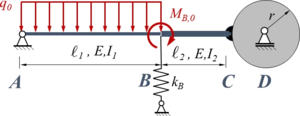
Das System ist eine Variante von Aufgabe TC12 . Hier ist eine Näherungslösung mit der Methode der Finiten Elemente gefragt. Das Sytem besteht aus zwei Sektionen mit den Längen ℓ1 bzw. ℓ2 sowie den Flächenmomenten I1 bzw. I2 . Sektion AB ist durch eine konstante Streckenlast q0 belastet, in B wirkt das Moment MB0 . Der Stab ist in A durch ein gelenkiges Festlager gelagert. In C ist das Stabende fest mit dem Umfang einer Rolle vom Radius r verbunden, die in D frei drehbar gelagert ist. In B sind die beiden Sektionen fest miteinander verbunden. Die Feder in B ist eine Translationsfeder mit der Steifigkeit kB .
Lageplan
Gesucht ist die FEM-Lösung mit zwei Elementen für den Euler-Bernoulli-Balken.
Die Systemparameter sind die gleichen wie in TC12, das dort gesuchte Flächenmoment I1 übernehmen wir zu
I
1
=
54
000
mm
4
{\displaystyle I_{1}=54\,000{\text{ mm}}^{4}}
.
Lösung mit Maxima
tmp
Wir suchen eine Lösung mit den Standard-Trial-Functions (Hermitesche-Polynome) für einen Euler-Bernoulli-Balken . Aufpassen müssen wir am Rand "C ". Hier sind Verschiebung und Verdrehung durch die Rolle gekoppelt. Die Element-Steifigkeitsmatrix müssen wir passend umschreiben.
Text
tmp
Wir übernehmen die Systemparameter aus TC12 zu
ℓ
1
=
1000
⋅
m
m
,
ℓ
2
=
ℓ
1
2
,
r
=
ℓ
1
4
,
E
=
210000.0
⋅
N
m
m
2
,
I
1
=
54000
⋅
m
m
4
,
I
2
=
2
⋅
I
1
,
k
B
=
3
⋅
I
1
⋅
E
ℓ
1
3
,
q
0
=
10
⋅
N
m
m
,
M
B
=
q
0
⋅
ℓ
1
2
{\displaystyle {\begin{array}{l}\displaystyle {\ell _{1}}=1000\cdot {\mathit {mm}},\\\displaystyle {\ell _{2}}={\frac {\ell _{1}}{2}},\\\displaystyle r={\frac {\ell _{1}}{4}},\\\displaystyle E={\frac {210000.0\cdot N}{{\mathit {mm}}^{2}}},\\\displaystyle {{I}_{1}}=54000\cdot {{\mathit {mm}}^{4}},\\\displaystyle {{I}_{2}}=2\cdot {{I}_{1}},\\\displaystyle {{k}_{B}}={\frac {3\cdot {{I}_{1}}\cdot E}{\ell _{1}^{3}}},\\\displaystyle {{q}_{0}}={\frac {10\cdot N}{\mathit {mm}}},\\\displaystyle {{M}_{B}}={{q}_{0}}\cdot {\ell _{1}^{2}}\end{array}}}
,
und wählen als Referenzgröße wref für die Auslenkung des Balkens die maximale Verschiebung eines Kragbalkens unter konstanter Streckenlast :
w
r
e
f
=
q
o
ℓ
1
4
8
E
I
1
{\displaystyle \displaystyle w_{ref}={\frac {q_{o}\;\ell _{1}^{4}}{8\;E\,I_{1}}}}
Declarations
Text
tmp
Die Trial-Functions je Element "i " zur Komposition der Form-Funktion kopieren wir aus Finite Elemente Methode zu
ϕ
1
=
2
⋅
ξ
3
−
3
⋅
ξ
2
+
1
,
ϕ
2
=
ℓ
i
⋅
(
ξ
3
−
2
⋅
ξ
2
+
ξ
)
,
ϕ
3
=
3
⋅
ξ
2
−
2
⋅
ξ
3
,
ϕ
4
=
ℓ
i
⋅
(
ξ
3
−
ξ
2
)
{\displaystyle {\begin{array}{l}\phi _{1}=2\cdot {{\xi }^{3}}-3\cdot {{\xi }^{2}}+1,\\\phi _{2}={{\ell }_{i}}\cdot \left({{\xi }^{3}}-2\cdot {{\xi }^{2}}+\xi \right),\\\phi _{3}=3\cdot {{\xi }^{2}}-2\cdot {{\xi }^{3}},\\\phi _{4}={{\ell }_{i}}\cdot \left({{\xi }^{3}}-{{\xi }^{2}}\right)\end{array}}}
,
die Koordinaten der Verschiebung sind
Q
i
=
(
W
i
−
1
Φ
i
−
1
W
i
Φ
i
)
{\displaystyle Q_{i}=\left({\begin{array}{l}W_{i-1}\\\Phi _{i-1}\\W_{i}\\\Phi _{i}\end{array}}\right)}
.
Damit ist
w
i
(
x
i
)
=
W
i
−
1
⋅
(
2
⋅
ξ
3
−
3
⋅
ξ
2
+
1
)
+
Φ
i
−
1
⋅
ℓ
i
⋅
(
ξ
3
−
2
⋅
ξ
2
+
ξ
)
+
W
i
⋅
(
3
⋅
ξ
2
−
2
⋅
ξ
3
)
+
Φ
i
⋅
ℓ
i
⋅
(
ξ
3
−
ξ
2
)
{\displaystyle {\begin{array}{lcll}w_{i}(x_{i})=&&W_{i-1}&\cdot \left(2\cdot {{\xi }^{3}}-3\cdot {{\xi }^{2}}+1\right)\\&+&\Phi _{i-1}&\cdot {{\ell }_{i}}\cdot \left({{\xi }^{3}}-2\cdot {{\xi }^{2}}+\xi \right)\\&+&W_{i}&\cdot \left(3\cdot {{\xi }^{2}}-2\cdot {{\xi }^{3}}\right)\\&+&\Phi _{i}&\cdot {{\ell }_{i}}\cdot \left({{\xi }^{3}}-{{\xi }^{2}}\right)\end{array}}}
.
Formfunctions
Text
tmp
Die Gleichgewichtsbedingungen kommen aus dem Prinzip der virtuellen Verrückungen zu
δ
W
=
!
0
=
δ
W
a
−
δ
Π
{\displaystyle {\begin{array}{ll}\delta W&{\stackrel {!}{=}}0\\&=\delta W_{a}-\delta \Pi \end{array}}}
.
Wir sortieren die Elemente der virtuellen Arbeit nach den virtuellen Koordinaten und den Koordinaten des System und konstruieren daraus das gewöhnliche Gleichungssystem
K
_
_
⋅
Q
_
=
P
_
{\displaystyle {\underline {\underline {K}}}\cdot {\underline {Q}}={\underline {P}}}
.
Die Anteile an der gesamten virtuellen Arbeit kommen aus der virtuellen Formänderungsenergie δΠ und der virtuellen Arbeit der äußeren Lasten δWa .
Dabei ist für unsere zwei Elemente δΠ = δΠ1 + δΠ2 ' mit
δ
Π
i
=
δ
Q
_
i
T
⋅
k
_
_
0
⋅
Q
i
_
{\displaystyle \delta \Pi _{i}=\delta {\underline {Q}}_{i}^{T}\cdot {\underline {\underline {k}}}_{0}\cdot {\underline {Q_{i}}}}
und der Element-Steifigkeitsmatrix
k
_
_
0
=
E
I
ℓ
i
3
⋅
(
12
6
⋅
ℓ
i
−
12
6
⋅
ℓ
i
6
⋅
ℓ
i
4
⋅
ℓ
i
2
−
6
⋅
ℓ
i
2
⋅
ℓ
i
2
−
12
−
6
⋅
ℓ
i
12
−
6
⋅
ℓ
i
6
⋅
ℓ
i
2
⋅
ℓ
i
2
−
6
⋅
ℓ
i
4
⋅
ℓ
i
2
)
{\displaystyle {\underline {\underline {k}}}_{0}=\displaystyle {\frac {\mathit {EI}}{{\ell }_{i}^{3}}}\cdot {\begin{pmatrix}12&6\cdot {{\ell }_{i}}&-12&6\cdot {{\ell }_{i}}\\6\cdot {{\ell }_{i}}&4\cdot {{\ell }_{i}^{2}}&-6\cdot {{\ell }_{i}}&2\cdot {{\ell }_{i}^{2}}\\-12&-6\cdot {{\ell }_{i}}&12&-6\cdot {{\ell }_{i}}\\6\cdot {{\ell }_{i}}&2\cdot {{\ell }_{i}^{2}}&-6\cdot {{\ell }_{i}}&4\cdot {{\ell }_{i}^{2}}\end{pmatrix}}}
.
Für Element 1 können wir diese Matrix direkt übernehmen, das heißt k1 = k0 für i=1.
Element 2 birgt eine Tücke: Hier sind Verschiebung W2 und Verdrehung Φ2 gekoppelt über die Kinematik der Rolle:
W
2
=
−
r
⋅
Φ
2
{\displaystyle W_{2}=-r\cdot \Phi _{2}}
Damit ist auch die Variation in diesen Koordinaten gekoppelt, also
δ
W
2
=
−
r
⋅
δ
Φ
2
{\displaystyle \delta W_{2}=-r\cdot \delta \Phi _{2}}
.
Mit dieser Beziehung eliminieren wir demnach W2 aus der Formulierung der Gleichgewichtsbedingungen. Das Einsetzen der kinematischen Beziehungen in δΠ liefert nun als Element-Steifigkeitsmatrix
k
_
_
2
=
E
I
2
l
2
3
⋅
(
12
6
⋅
ℓ
2
0
12
⋅
r
+
6
⋅
ℓ
2
6
⋅
ℓ
2
4
⋅
ℓ
2
2
0
6
⋅
ℓ
2
⋅
r
+
2
⋅
ℓ
2
2
0
0
0
0
12
⋅
r
+
6
⋅
ℓ
2
6
⋅
ℓ
2
⋅
r
+
2
⋅
ℓ
2
2
0
12
⋅
r
2
+
12
⋅
ℓ
2
⋅
r
+
4
⋅
ℓ
2
2
)
{\displaystyle {\underline {\underline {k}}}_{2}=\displaystyle {\frac {E\,I_{2}}{l_{2}^{3}}}\cdot {\begin{pmatrix}12&6\cdot {{\ell }_{2}}&0&12\cdot r+6\cdot {{\ell }_{2}}\\6\cdot {{\ell }_{2}}&4\cdot {{\ell }_{2}^{2}}&0&6\cdot {{\ell }_{2}}\cdot r+2\cdot {{\ell }_{2}^{2}}\\0&0&0&0\\12\cdot r+6\cdot {{\ell }_{2}}&6\cdot {{\ell }_{2}}\cdot r+2\cdot {{\ell }_{2}^{2}}&0&12\cdot {{r}^{2}}+12\cdot {{\ell }_{2}}\cdot r+4\cdot {{\ell }_{2}^{2}}\end{pmatrix}}}
,
bei der die Elemente der dritten Zeile (zu δWi ) und der dritten Spalte (zu Wi ) verschwinden.
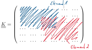
Struktur der Steifigkeitsmatrix. Wir setzen die Gesamt-Steifigkeitsmatrix K aus den beiden Element-Steifigkeitsmatrizen so zusammen:
Und das ist die anteilige Gesamt-Steifigkeitsmatrix der beiden Balken-Abschnitte:
K
_
_
=
(
12
⋅
I
1
⋅
E
ℓ
1
3
6
⋅
I
1
⋅
E
ℓ
1
2
−
12
⋅
I
1
⋅
E
ℓ
1
3
6
⋅
I
1
⋅
E
ℓ
1
2
0
0
6
⋅
I
1
⋅
E
ℓ
1
2
4
⋅
I
1
⋅
E
ℓ
1
−
6
⋅
I
1
⋅
E
ℓ
1
2
2
⋅
I
1
⋅
E
ℓ
1
0
0
−
12
⋅
I
1
⋅
E
ℓ
1
3
−
6
⋅
I
1
⋅
E
ℓ
1
2
12
⋅
I
2
⋅
E
ℓ
2
3
+
12
⋅
I
1
⋅
E
ℓ
1
3
6
⋅
I
2
⋅
E
ℓ
2
2
−
6
⋅
I
1
⋅
E
ℓ
1
2
0
12
⋅
I
2
⋅
r
⋅
E
ℓ
2
3
+
6
⋅
I
2
⋅
E
ℓ
2
2
6
⋅
I
1
⋅
E
ℓ
1
2
2
⋅
I
1
⋅
E
ℓ
1
6
⋅
I
2
⋅
E
ℓ
2
2
−
6
⋅
I
1
⋅
E
ℓ
1
2
4
⋅
I
2
⋅
E
ℓ
2
+
4
⋅
I
1
⋅
E
ℓ
1
0
6
⋅
I
2
⋅
r
⋅
E
ℓ
2
2
+
2
⋅
I
2
⋅
E
ℓ
2
0
0
0
0
0
0
0
0
12
⋅
I
2
⋅
r
⋅
E
ℓ
2
3
+
6
⋅
I
2
⋅
E
ℓ
2
2
6
⋅
I
2
⋅
r
⋅
E
ℓ
2
2
+
2
⋅
I
2
⋅
E
ℓ
2
0
12
⋅
I
2
⋅
r
2
⋅
E
ℓ
2
3
+
12
⋅
I
2
⋅
r
⋅
E
ℓ
2
2
+
4
⋅
I
2
⋅
E
ℓ
2
)
{\displaystyle {\underline {\underline {K}}}\,=\,{\begin{pmatrix}{\frac {12\cdot {{I}_{1}}\cdot E}{{\ell }_{1}^{3}}}&{\frac {6\cdot {{I}_{1}}\cdot E}{{\ell }_{1}^{2}}}&-{\frac {12\cdot {{I}_{1}}\cdot E}{{\ell }_{1}^{3}}}&{\frac {6\cdot {{I}_{1}}\cdot E}{{\ell }_{1}^{2}}}&0&0\\{\frac {6\cdot {{I}_{1}}\cdot E}{{\ell }_{1}^{2}}}&{\frac {4\cdot {{I}_{1}}\cdot E}{{\ell }_{1}}}&-{\frac {6\cdot {{I}_{1}}\cdot E}{{\ell }_{1}^{2}}}&{\frac {2\cdot {{I}_{1}}\cdot E}{{\ell }_{1}}}&0&0\\-{\frac {12\cdot {{I}_{1}}\cdot E}{{\ell }_{1}^{3}}}&-{\frac {6\cdot {{I}_{1}}\cdot E}{{\ell }_{1}^{2}}}&{\frac {12\cdot {{I}_{2}}\cdot E}{{\ell }_{2}^{3}}}+{\frac {12\cdot {{I}_{1}}\cdot E}{{\ell }_{1}^{3}}}&{\frac {6\cdot {{I}_{2}}\cdot E}{{\ell }_{2}^{2}}}-{\frac {6\cdot {{I}_{1}}\cdot E}{{\ell }_{1}^{2}}}&0&{\frac {12\cdot {{I}_{2}}\cdot r\cdot E}{{\ell }_{2}^{3}}}+{\frac {6\cdot {{I}_{2}}\cdot E}{{\ell }_{2}^{2}}}\\{\frac {6\cdot {{I}_{1}}\cdot E}{{\ell }_{1}^{2}}}&{\frac {2\cdot {{I}_{1}}\cdot E}{{\ell }_{1}}}&{\frac {6\cdot {{I}_{2}}\cdot E}{{\ell }_{2}^{2}}}-{\frac {6\cdot {{I}_{1}}\cdot E}{{\ell }_{1}^{2}}}&{\frac {4\cdot {{I}_{2}}\cdot E}{{\ell }_{2}}}+{\frac {4\cdot {{I}_{1}}\cdot E}{{\ell }_{1}}}&0&{\frac {6\cdot {{I}_{2}}\cdot r\cdot E}{{\ell }_{2}^{2}}}+{\frac {2\cdot {{I}_{2}}\cdot E}{{\ell }_{2}}}\\0&0&0&0&0&0\\0&0&{\frac {12\cdot {{I}_{2}}\cdot r\cdot E}{{\ell }_{2}^{3}}}+{\frac {6\cdot {{I}_{2}}\cdot E}{{\ell }_{2}^{2}}}&{\frac {6\cdot {{I}_{2}}\cdot r\cdot E}{{\ell }_{2}^{2}}}+{\frac {2\cdot {{I}_{2}}\cdot E}{{\ell }_{2}}}&0&{\frac {12\cdot {{I}_{2}}\cdot {{r}^{2}}\cdot E}{{\ell }_{2}^{3}}}+{\frac {12\cdot {{I}_{2}}\cdot r\cdot E}{{\ell }_{2}^{2}}}+{\frac {4\cdot {{I}_{2}}\cdot E}{{\ell }_{2}}}\end{pmatrix}}}
Auch die Feder ist ein elastisches Element und trägt damit eine virtuelle Formänderungsenergie, zu δΠ hinzu, nämlich
δ
Π
3
=
k
B
W
1
⋅
δ
W
1
{\displaystyle \delta \Pi _{3}=k_{B}\,W_{1}\cdot \delta W_{1}}
Diesen Beitrag müssen wir in Zeile 3, Spalte 3 hinzuaddieren, also mit der Anweisung
K
3
,
3
=
K
3
,
3
+
k
B
{\displaystyle K_{3,3}=K_{3,3}+k_{B}}
.
Auf der rechten Seite des Gleichungssystem bleiben die Beiträge der virtuellen Arbeiten äußerer Lasten stehen. Dies sind
δ
W
a
=
∫
ℓ
1
q
0
⋅
δ
w
(
x
)
d
x
+
M
B
⋅
δ
Φ
1
{\displaystyle \delta W^{a}=\int _{\ell _{1}}q_{0}\cdot \delta w(x)\,dx+M_{B}\cdot \delta \Phi _{1}}
,
wir erhalten
P
_
=
(
q
0
⋅
ℓ
1
2
q
0
⋅
ℓ
1
2
12
q
0
⋅
ℓ
1
2
M
B
−
q
0
⋅
ℓ
1
2
12
0
0
)
{\displaystyle {\underline {P}}\,=\,{\begin{pmatrix}\displaystyle {\frac {{{q}_{0}}\cdot {{\ell }_{1}}}{2}}\\\displaystyle {\frac {{{q}_{0}}\cdot {{\ell }_{1}^{2}}}{12}}\\\displaystyle {\frac {{{q}_{0}}\cdot {{\ell }_{1}}}{2}}\\\displaystyle {{M}_{B}}-{\frac {{{q}_{0}}\cdot {{\ell }_{1}^{2}}}{12}}\\\displaystyle 0\\\displaystyle 0\end{pmatrix}}}
.
Jetzt fehlen nur noch die Randbedingungen. Wir setzen
W
0
=
0
{\displaystyle W_{0}=0}
,
die kinematische Beziehung
W
2
=
−
r
⋅
Φ
2
{\displaystyle W_{2}=-r\cdot \Phi _{2}}
haben wir schon eingearbeit - bleibt also nur noch, die entsprechenden Spalten und Zeilen in den Matrizen K, Q und P zu eliminieren. Es bleibt das Gleichungssystem
(
4
⋅
I
1
⋅
E
ℓ
1
−
6
⋅
I
1
⋅
E
ℓ
1
2
2
⋅
I
1
⋅
E
ℓ
1
0
−
6
⋅
I
1
⋅
E
ℓ
1
2
12
⋅
I
2
⋅
E
ℓ
2
3
+
12
⋅
I
1
⋅
E
ℓ
1
3
+
k
B
6
⋅
I
2
⋅
E
ℓ
2
2
−
6
⋅
I
1
⋅
E
ℓ
1
2
12
⋅
I
2
⋅
r
⋅
E
ℓ
2
3
+
6
⋅
I
2
⋅
E
ℓ
2
2
2
⋅
I
1
⋅
E
ℓ
1
6
⋅
I
2
⋅
E
ℓ
2
2
−
6
⋅
I
1
⋅
E
ℓ
1
2
4
⋅
I
2
⋅
E
ℓ
2
+
4
⋅
I
1
⋅
E
ℓ
1
6
⋅
I
2
⋅
r
⋅
E
ℓ
2
2
+
2
⋅
I
2
⋅
E
ℓ
2
0
12
⋅
I
2
⋅
r
⋅
E
ℓ
2
3
+
6
⋅
I
2
⋅
E
ℓ
2
2
6
⋅
I
2
⋅
r
⋅
E
ℓ
2
2
+
2
⋅
I
2
⋅
E
ℓ
2
12
⋅
I
2
⋅
r
2
⋅
E
ℓ
2
3
+
12
⋅
I
2
⋅
r
⋅
E
ℓ
2
2
+
4
⋅
I
2
⋅
E
ℓ
2
)
⋅
(
Φ
0
W
1
Φ
1
Φ
2
)
=
(
q
0
⋅
ℓ
1
2
12
q
0
⋅
ℓ
1
2
M
B
−
q
0
⋅
ℓ
1
2
12
0
)
{\displaystyle {\begin{pmatrix}{\frac {4\cdot {{I}_{1}}\cdot E}{{\ell }_{1}}}&-{\frac {6\cdot {{I}_{1}}\cdot E}{{\ell }_{1}^{2}}}&{\frac {2\cdot {{I}_{1}}\cdot E}{{\ell }_{1}}}&0\\-{\frac {6\cdot {{I}_{1}}\cdot E}{{\ell }_{1}^{2}}}&{\frac {12\cdot {{I}_{2}}\cdot E}{{\ell }_{2}^{3}}}+{\frac {12\cdot {{I}_{1}}\cdot E}{{\ell }_{1}^{3}}}+{{k}_{B}}&{\frac {6\cdot {{I}_{2}}\cdot E}{{\ell }_{2}^{2}}}-{\frac {6\cdot {{I}_{1}}\cdot E}{{\ell }_{1}^{2}}}&{\frac {12\cdot {{I}_{2}}\cdot r\cdot E}{{\ell }_{2}^{3}}}+{\frac {6\cdot {{I}_{2}}\cdot E}{{\ell }_{2}^{2}}}\\{\frac {2\cdot {{I}_{1}}\cdot E}{{\ell }_{1}}}&{\frac {6\cdot {{I}_{2}}\cdot E}{{\ell }_{2}^{2}}}-{\frac {6\cdot {{I}_{1}}\cdot E}{{\ell }_{1}^{2}}}&{\frac {4\cdot {{I}_{2}}\cdot E}{{\ell }_{2}}}+{\frac {4\cdot {{I}_{1}}\cdot E}{{\ell }_{1}}}&{\frac {6\cdot {{I}_{2}}\cdot r\cdot E}{{\ell }_{2}^{2}}}+{\frac {2\cdot {{I}_{2}}\cdot E}{{\ell }_{2}}}\\0&{\frac {12\cdot {{I}_{2}}\cdot r\cdot E}{{\ell }_{2}^{3}}}+{\frac {6\cdot {{I}_{2}}\cdot E}{{\ell }_{2}^{2}}}&{\frac {6\cdot {{I}_{2}}\cdot r\cdot E}{{\ell }_{2}^{2}}}+{\frac {2\cdot {{I}_{2}}\cdot E}{{\ell }_{2}}}&{\frac {12\cdot {{I}_{2}}\cdot {{r}^{2}}\cdot E}{{\ell }_{2}^{3}}}+{\frac {12\cdot {{I}_{2}}\cdot r\cdot E}{{\ell }_{2}^{2}}}+{\frac {4\cdot {{I}_{2}}\cdot E}{{\ell }_{2}}}\end{pmatrix}}\,\cdot \,{\begin{pmatrix}{{\Phi }_{0}}\\{{W}_{1}}\\{{\Phi }_{1}}\\{{\Phi }_{2}}\end{pmatrix}}\,=\,{\begin{pmatrix}{\frac {{{q}_{0}}\cdot {{\ell }_{1}^{2}}}{12}}\\{\frac {{{q}_{0}}\cdot {{\ell }_{1}}}{2}}\\{{M}_{B}}-{\frac {{{q}_{0}}\cdot {{\ell }_{1}^{2}}}{12}}\\0\end{pmatrix}}}
.
Equilibrium Conditions
Text
tmp
Auflösen nach Q liefert
Φ
0
=
−
0.0157
,
W
1
=
−
4.86
⋅
10
−
18
m
,
Φ
1
=
+
0.0682
,
Φ
2
=
−
0.0262
{\displaystyle {\begin{array}{ll}{\Phi _{0}}&=-0.0157,\\W_{1}&=-4.86\cdot {{10}^{-18}}\;{\text{m}},\\{\Phi _{1}}&=+0.0682,\\{\Phi _{2}}&=-0.0262\end{array}}}
,
zusammen mit den Randbedingungen also
W
0
=
0
,
Φ
0
=
−
0.0157
,
W
1
=
−
4.86
⋅
10
−
18
m
,
Φ
1
=
+
0.0682
,
W
2
=
+
0.00656
m
,
Φ
2
=
−
0.0262
{\displaystyle {\begin{array}{ll}{\color {green}{W_{0}}}&={\color {green}{0}},\\{\Phi _{0}}&=-0.0157,\\W_{1}&=-4.86\cdot {{10}^{-18}}\;{\text{m}},\\{\Phi _{1}}&=+0.0682,\\{\color {green}{W_{2}}}&={\color {green}{+0.00656{\text{ m}}}},\\{\Phi _{2}}&=-0.0262\end{array}}}
.
Solving
Text
tmp
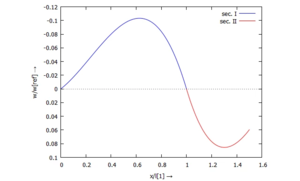
Biegelinie w(x) Die Auslenkung w(x) der Querschnitte tragen wir jetzt auf. Für die dimensionslose Darstellung wählen wir aus der analytischen Lösung für den Kragbalken unter konstanter Streckenlast
w
r
e
f
=
q
0
⋅
ℓ
1
4
8
⋅
E
I
1
=
0.11
m
{\displaystyle {\begin{array}{ll}{{w}_{\mathit {ref}}}&\displaystyle ={\frac {{{q}_{0}}\cdot {{\ell }_{1}^{4}}}{8\cdot E\,{{I}_{1}}}}\\&=0.11{\text{ m}}\end{array}}}
und tragen w(x)/wref auf:
Die maximale Auslenkung des Systems ist dann
w
m
a
x
≈
0.1
⋅
0.11
m
≈
11
mm
{\displaystyle {\begin{array}{ll}w_{max}&\approx 0.1\cdot 0.11{\text{ m}}\\&\approx 11{\text{ mm}}\end{array}}}
,
und das entspricht der Vorgabe aus Aufgabe TC12 .
Post-Processing
Text
Links
Literature