Gelöste Aufgaben/JUMP/E-Motor and Drive-Train: Unterschied zwischen den Versionen
< Gelöste Aufgaben | JUMP
Keine Bearbeitungszusammenfassung |
|||
| Zeile 3: | Zeile 3: | ||
==Scope== | ==Scope== | ||
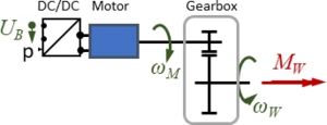
[[Datei:JUMP-E-Motor and Drive Train.png|mini|Diagram: E-Motor and Drive Train]] | [[Datei:JUMP-E-Motor and Drive Train.png|mini|Diagram: E-Motor and Drive Train]]The Drive-Train consists of a DC/DC-converter, a DC Motor and a gear-box. | ||
* '''DC/DC-converter''': is supplied with the battery voltage ''U<sub>B</sub>'', the output voltage is controlled by the driver via setpoint “''p''“. | |||
* '''motor''': is a standard DC brushed motor, the manufacturer provides only few information on its characteristics - we’ll need to improvise. | |||
* '''gearbox''': has a gear ratio of ratio of ''n<sub>G</sub>''=100, its shaft rotates at speed ''ω<sub>W</sub>'' and delivers a torque ''M<sub>W</sub>'' to the front wheels. | |||
The task is: provide a mathematical model for the drive train that accounts for load-alterations imposed by the driver. And we assume losses in the two converters - DC/DC and gearbox - to be negligible. | |||
==Structure== | ==Structure== | ||
[[Datei:JUMP-drivetrain-blockdiagram.png|mini|150x150px|Block diagram]] | |||
The drive train receives a "gas"-pedal position "p" from the driver and a battery-voltage ''U<sub>B</sub>''. | |||
It delivers a torque ''M<sub>W</sub>'' on the wheel and creates an electric current ''I<sub>M</sub>'' through the motor. | |||
[[Datei:JUMP-drivetrain-exploded.png|links|mini|Drive-train components.]] | |||
The sub-model consists of DC/DC-converter, Motor and gear-box: | |||
===DC/DC Converter=== | |||
===Motor=== | |||
===Gearbox=== | |||
==Model== | ==Model== | ||
<!------------------------------------------------------------------------->==tmp== | |||
{{MyCodeBlock | |||
|title=Electrical Components | |||
|text=Text | |||
|code= | |||
<syntaxhighlight lang="lisp" line start=1> | |||
1+1=2 | |||
</syntaxhighlight> | |||
}} | |||
<!------------------------------------------------------------------------->==tmp== | |||
{{MyCodeBlock | |||
|title=Mechanical Components | |||
|text=Text | |||
|code= | |||
<syntaxhighlight lang="lisp" line start=1> | |||
1+1=2 | |||
</syntaxhighlight> | |||
}} | |||
==Variables== | ==Variables== | ||
Version vom 10. März 2021, 14:18 Uhr
Scope

The Drive-Train consists of a DC/DC-converter, a DC Motor and a gear-box.
- DC/DC-converter: is supplied with the battery voltage UB, the output voltage is controlled by the driver via setpoint “p“.
- motor: is a standard DC brushed motor, the manufacturer provides only few information on its characteristics - we’ll need to improvise.
- gearbox: has a gear ratio of ratio of nG=100, its shaft rotates at speed ωW and delivers a torque MW to the front wheels.
The task is: provide a mathematical model for the drive train that accounts for load-alterations imposed by the driver. And we assume losses in the two converters - DC/DC and gearbox - to be negligible.
Structure

The drive train receives a "gas"-pedal position "p" from the driver and a battery-voltage UB.
It delivers a torque MW on the wheel and creates an electric current IM through the motor.

The sub-model consists of DC/DC-converter, Motor and gear-box:
DC/DC Converter
Motor
Gearbox
Model
tmp
Electrical Components
Text
1+1=2
tmp
Mechanical Components
Text
1+1=2
Variables
Parameter
>
References
- ...